Just like most things in life, industrial grade 3D scanners are not a “one size fits all” solution. For that reason, there are a variety of scanner classes and types. Choosing the right one can mean all the difference in making your next project a success. In this post we will be talking about the most common class of scanner used in the industry. This class of scanner is designed to capture complex 3D shapes on objects ranging from the size of a coin to objects as large as a dozen feet across. They can capture millions of points per second and the finished scan may contain upwards of 50 to 100 million individual data points. This allows these scanners to create highly detailed scans that can render everything from basic primitive shapes, all the way to complex lofted surfaces like power turbine blades. They are also useful in creating scans of organic shapes such as natural formations and handmade sculptures. These scanners have no physical contact with the part being scanned and have an accuracy ranging from 0.0005” to about 0.005”.
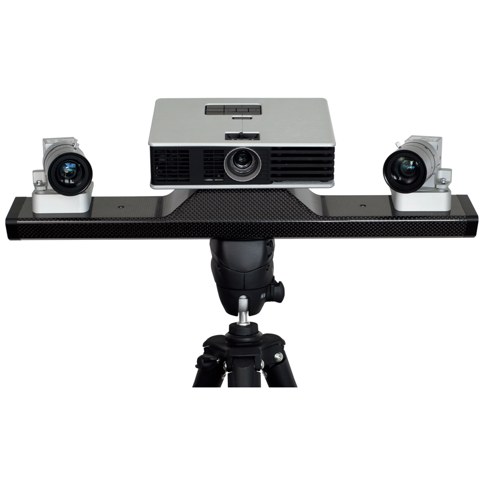
The first type of scanner up for discussion in this class, is the structured light scanner (also called a blue light or white light scanner). These units use a projector and either one, two or three cameras to create the scan. By projecting a series of lines on the object, it can use the cameras, set at a fixed distance and angle, to extrapolate the position of the lines. They can produce a scan in as little as half a second, with millions of data points. Because these scanners rely on not only the projector, but the cameras to see the object at the same time, line-of-site is a physical necessity. If you are only needing to take a single image of one side of an object, then your job may be done. Most of the time you will require more than that. So, by taking a series of scans from different angles around the part, the scanner tech will get a series of individual scans ranging from just a few to 100s of scans. The software will then run through an advanced algorithm that looks for overlapping data and will stich the images together just like a jig saw puzzle. The software typically needs some manual intervention for the tech to get the scans roughly aligned before it can make the alignment process successful. Because these scanners rely entirely on the scan data in order to align the multiple scans, they must have enough overlap, as well as unique features, for the software to lock in on all three planes and all three axis to get a good alignment. Sometimes object, that have long, flat machined surfaces or other primitive features, such as cylinders or spheres, make it almost impossible to get a good alignment. For objects like that, it is not uncommon to add additional features to the part before scanning, so that the software has additional features to “lock on to”. We have seen and used things ranging from ping pong balls, to airsoft pellets, to modeling clay.
Take a look at the photo below:
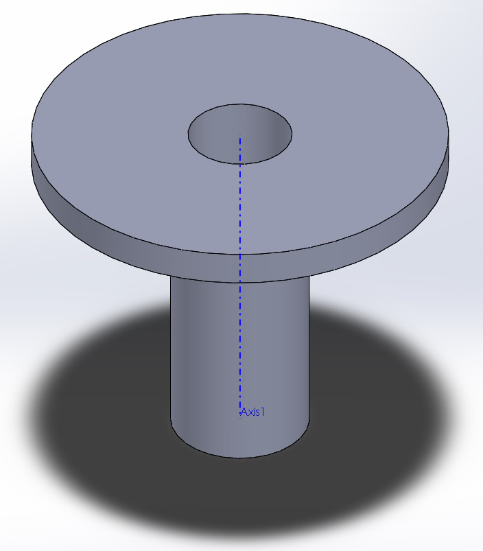
It is representative of an amazingly simple part. So simple in fact, that I would probably just get out a set of calipers to measure it and then draw it from scratch. Sometimes that can be faster than scanning it. But, for the sake of this example, let us say that I need to scan a part with this basic shape that looks like a pipe flange. Scanning it from the end, it looks like a flat piece of machined metal with a cylinder cut out in the middle. If you were to take scans from all the way around the flange, they would all be able to align to the flat plane of the flange, and to the edge where it meets the cylinder. However, it would be nearly impossible to lock each individual scan along the axis coming straight out of the cylinder. For that, you would need to add some modeling clay or pellets, randomly attached to the flat surface of the flange. This gives it geometry to align to. From there, those added features can be removed in post processing, or when reverse engineering the part in specialized CAD software.
Another type of shape that this type of scanner struggles with are thin pieces that need to be scanned on both sides. Think of something like a stamped piece of sheet metal. The reason being, that all the software knows, is to try and find a “best fit” from the scan provided. If it gets two almost identical set of scans that are set 1/16” to ¼” apart, the scanner will try to mesh them together. If it is just a stamped piece of sheet metal, you can typically just scan one side and then extrude it out in CAD when you re-draw it. If there are stand-offs or mounts welded on both side of the piece, it can be extremely hard to get it all aligned relative to both sides. These scanners can also have trouble with glossy, black and clear objects. Because it needs to be able to see the pattern the projector casts on the part, the shiny and clear surfaces will have trouble being scanned. The best fix for this, is an aerosol can of developer powder designed for welders to look for cracks (https://www.magnaflux.com/Products/SKD-S2.htm). It is basically talcum powder suspended in alcohol. It sprays a very thin, wet layer, and within seconds the alcohol evaporates leaving you with a white powdery matte finish that just wipes off when you are done scanning. The last type of model that these scanners have issues with are large pieces. Because each scan that is aligned introduces a little error, the longer the chain of scans, the more error introduced.
The bread and butter for this type of scanner is parts with complex shapes that are anywhere from 1” to about 24” square. Most of the time the scanners are equipped to operate a stepper motor equipped rotary table. Just setup the scanner on a tripod with an isometric view of the turn table deck, and you are ready to go. They can be set to take anywhere from 4 to over 100 scans in 360 degrees around the part automatically. It can then triangulate the basic location of each scan, then use its software to mesh the scans together. Next, just flip the part over, scan the back side 360 degree, and connect the two sets of scans together to get a near watertight scan. Watertight, meaning that there are no holes in it. Because scans have no thickness and are just a surface, they are required to be watertight, if they are to be printed in a 3D printer. We have had dozens of similar sized parts come in, that when setup can be scanned 360 degrees, flipped, the other side scanned 360 degrees, then mated together. It may only take a few minutes and is highly repeatable. These scanners seem to align these types of parts better also. Because the scans come around 360 degrees, the first scan overlaps with the last scan, making it much tighter and more accurate. It works much better than just having one long set of scans like we mentioned above. Those scans are only meshed on one end, and the first scan is only connected to the last scan from all the other scans in between. By having scans that wrap all the way around, it all just seems to work out better.
Structured light scanners come in two basic form factors. Handheld and tripod mounted. The most popular handheld model is by far the Artec brand of scanners (artec3d.com). Instead of taking one scan at a time, it takes multiple scans in quick succession and you track the scanner over the part in a spray-painting motion. The idea being that because the scans are taken so quickly, they are guaranteed to have a large percentage of overlap. The computer, either tethered to (older Artec Eva) or built into the hand unit (newest Artec Leo), processes the images and stores them in a point cloud until they can be offloaded to a full-sized powerful PC. The PC will process, align, and clean up the files for export. These are great for scanning larger objects or people. They are a good mixture of speed, accuracy and detail. A quality tripod mounted unit will, in most cases, offer higher detail and better accuracy at the cost of speed and ease of use. Our go-to unit for most applications is the Polyga (formerly HDI Advanced) series of scanners (polyga.com/carbon-3d-scanner). They are end user adjustable so that you can adjust the field of view (how wide the scanner can see in one scan) up or down to give a larger image, or a smaller field of view for smaller parts. Because the number of pixels stays the same, the pixel density (how many data points in each size, typically measured in cubic inches) increases with the smaller size. It is basically like having three different scanners in one. You can scan something the size of a car fender, then in about 15 minutes, reconfigure the scanner to scan something the size of a bottle cap. They even make a macro kit that allows you to use the same cameras with a small projector and telephoto lenses. With that kit, you can scan objects as small as a piece of jewelry, with remarkable detail. In our opinion, there is no other scanner on the market with as much versatility or quality for the price. Again, these scanners do give a better overall scan, but they are more labor intensive to operate. They really shine when coupled with a motorized turn table and when scanning those parts that are 1 to 24 cubic inches in overall size. They can scan larger parts, but typically the Artec can scan those parts faster, with just a little less detail and accuracy in the data. These two brands of scanners, in our opinion, are good entry-level scanners that can get you quality commercial grade scans in the $20,000 to $35,000 range. The undisputed king of structured light scanners must be the GOM range of scanners. Priced in the $100,000 to over $300,000 range, they are uniquely designed for high throughput, automated industrial quality control. They have arguably the best image quality in the industry and can be mated to things like, robotic arms, so that the scanner can be automatically positioned around a part to scan key areas. This is helpful in allowing you to compare a physical part to known standards, for non-destructive quality inspections.
As you can see, structured light scanners encompass a wide range of form factors, quality, and price. Even in this one type of scanner, they are not a one size fits all solution, because different models have their own strengths and weaknesses. If you have any questions, or are interested in acquiring a 3D scanner, don’t hesitate to give us a call. We have partnered with one of the largest US vendors for both the Artec and Polyga brands. So, not only can we provide you with great pricing, we can provide you the best post-purchase support in the industry. Remember, we don’t just sale these scanners, we use them every day in our own business.
In our next post, we are going to discuss my favorite all-around type of scanner for doing reverse engineering, the portable coordinate-measuring machine (P-CMM) with a laser scanning head. If you told me I could only have one type of scanner, it would be the P-CMM, and we will discuss why next time.